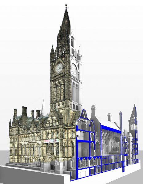
Over 1,400 3D Laser Scans used to model Neo-Gothic Building
Creating a detailed model of the Grade 1 Listed Manchester Town Hall using 3D Laser Scans to aid facilities management and design. The resulting 3D model is being used for managing this complex building, future restoration and as a historical record of this neo-gothic building.
The dedicated Hobs 3D team took over 1,400 unique 3D Laser Scans in a very tight deadline and within a heavily populated area, resulting in over 170GB of data. The resulting ‘point clouds’ were joined together to create a scan of the entire building. This resulting 3D scan was then used to draw a solid representation of the Town Hall buildings in the 3D software Revit 2015.
The brief was to create a ‘Level 3’ BIM model which contains the architectural details in enough detail to generate scale survey plans, sections and elevations. Hobs 3D led on the BIM integration process to streamline the project workflows.

3D Laser Scanning of Manchester Town Hall
Ged McNicholl, Associate Director, at Faithful + Gould explains: “The project required the development of data transfer between the 3D model, the asset management plan and a range of refurbishment redevelopment options for each room within the building. Hobs took a leading role in setting up the standards for the data transfer and developing the proof of concept with a number of interface software systems.”
The 3D laser scan survey consisted of a combination of conventional and cloud survey techniques resulting in the creation of a comprehensive 3D Revit model including building services and architectural features. A ‘proof of concept’ pilot was created to illustrate the geometric and data outputs. These were presented to Manchester City Council for approval, then formed the basis of the full project.
Ged comments “Hobs played an invaluable role in guiding the project team and the end client through all stages of the model development and delivery. They worked closely with all key stakeholders at the inception of the project to ensure the foundations for the model development were agreed and understood and maintained this commitment throughout.”
From Scans to Facilities Management
Initially, the building’s exterior (envelope) was modelled using the horizontal sections of the scans as reference. The start and end points for each wall were positioned with an accuracy of +/- 5mm across the length of the building. This process was repeated until the complete envelope was modelled.
This process was then repeated for the internal walls and spaces, until a simplified version of the building, free from decoration, was created; this ensured all space and rooms were accounted for.
Many of the architectural features especially arches, ceiling vaults and window reveals, appear uniform but were handmade originally, so each one is slightly different. The model captures this on an individual basis.
From this point, the facilities management or ‘cost-aiding’ element of the model was started, allowing for each room to report its Area, Perimeter, Volume and Wall Area. The addition of door and windows further increases the usefulness of this information, allowing calculation of opening widths, heights and areas. For example, doors were confirmed to be double or single and the swing direction was recorded.
Techniques were employed to apply significant detail to the model whilst maintaining sensible limits on file size and physical geometry.
Services and Feature Lighting, deemed to be of interest to the heritage of the building, were also modelled to be geometrically accurate, eg. cast-iron feature radiators in corridors.
Alongside the 3D Laser Scanning, at every location 360° panoramic views were captured that can be navigated in a similar fashion to Google StreetView. Dimensions can be taken from the imagery or notes added to any particular scan. This means that additional detail, such as door handles or balustrading can be viewed or measured in the original scan data.
In order to ensure overall quality of the model, a review process was established. This partly involved a room by room on-site check against a live version of the model, creating and acting on an amendments list. Within the model itself, each room is marked as confirming it has met with requirements.
Ged added “In addition to the planned site team, the project demanded flexible and reactive support from Hobs to meet the client’s needs and to adjust to on-going variations to the project. Hobs provided a dedicated team of site based resource and expert advisors throughout the duration of the project, this enabled the project team to meet the tight deadlines and client expectations as well as maintain strong working relationships under pressure.”
Hobs have since undertaken additional work to prime the model for use with the Authority’s existing facilities management systems. The opportunity to link asset information to the 3D model places the Authority in a position as leaders in efficiency and cost-saving. Hobs are also providing expert BIM support as the project enters into the next phase of development.
